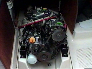
Yanmar 1GM10 diesel engine
zinc
|
|
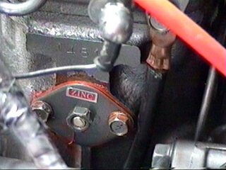
The engine zinc is located on the right as you are looking aft at the engine. (port side of the boat) The copper colored stuff around the zinc mounting plate is permatex ultra copper. It can handle the high temperatures generated by the engine. The zinc and the thermostat share a common sized gasket. It is a good idea to check the zinc once a year. Although Hake didn't include a shaft mounted zinc, I mounted one this year to protect the prop from corrosion. |
Figure 1 |
|
|
|
|||
water pump
|
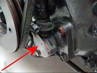
The water pump is located on the lower right as you are looking at the engine. The impeller can be accessed by removing three small bolts. You may need to replace the gasket every time you remove the cover. The impeller should be checked on an annual basis and removed during winter lay up. Install a new impeller by lining up the flat on the shaft and slowly insert while hand cranking the engine. This will insure that the vanes are oriented properly. You can use dish soap as a lubricant to make it easier to install. I replaced the seals on the water pump due to a water leak this past spring. The bearings felt a little rough so I went ahead and replaced them as well. I replace the impeller once a year. If you have a leaky water pump, check the oil line below the water pump to make sure it is not starting to rust. When water (especially salt) drips from the water pump and dries, the salt will attack the oil line. If you catch it in time, wire brush the excess rust and paint with Extend(Loctite product). If there is any doubt about the extent of the damage replace the line. |
Figure 2 |
Thermostat
|
It is recommended to replace the thermostat every three years. Since I had never replaced it before it was pretty corroded when I got to it. It uses the same gasket as the zinc mounting plate. I also used a light coat of permatex ultra copper with the gasket. |
Figure 3 |
|
Bleeding air from fuel system |
|
|
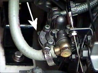
There are three places that you have to bleed air from in the fuel system. If a filter has just been replaced or line broken, you will have to bleed air from all the fuel lines. Locate the manual pump lever shown in the figure 4 on the right(arrow is pointing to it). The end of the lever is barely visible under the fuel pump. This will be used to pump fuel instead of running the engine. |
Figure 4 |
|---|---|
|
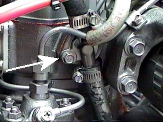
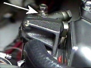
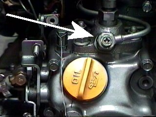
Loosen the bleed screw on top of the fuel filter shown in Figure 5. Now operate the fuel pump manually by pulling up on the lever and then releasing several times until fuel is visible with no air bubbles present. Catch any fuel that dribbles out from under the screw with a shop towel. Tighten the screw on top of the fuel filter housing and loosen the screw on top of the fuel injection pump shown in Figure 6. Operate the fuel pump manually with the lever as before until a steady stream of fuel is obtained with no air bubbles, then retighten. Repeat this step until all the air has been removed before proceeding to the next step. |
Figure 5 |
|
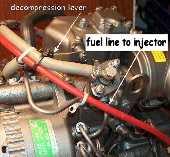
Loosen the line going into the fuel injector(see Figure 7). Pull up on the decompression lever(see Figure 7) and crank the engine by hand until fuel starts coming out of the line at the injector and then tighten. Start the engine. If the engine runs a little rough you may have to bleed more air out. This can be done with the engine running. Check for air at the fuel filter first, then the injector pump and finally at the fuel injector. Use extreme caution when working around a running engine and stay clear of the alternator belt and other moving parts. If you don't feel comfortable working around the engine while its running, then repeat the procedure with the engine off or have a professional mechanic do the work. |
Figure 6 |
|
Final Note: There is a nylon washer under each bleed screw. Do not over tighten! I would recommend a nut driver or a proper sized phillips screw driver be used. I stripped the threads on the fuel filter housing and had to replace it a couple of years ago. |
Figure 7 |
|
Vacuum Gage |
|
|
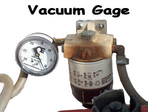
This vacuum gage should warn if the filter is getting dirty. I plan to change the filter around 1 or 1 1/2 inches of Hg. Normally it runs around 1/2 " or less. I installed the gage right after a filter change. I won't be able to confirm this works until I have to replace the fuel filter. I always carry a spare. |
|
Yanmar Part numbers:
engine mounted fuel filter: 104500-55710
water pump impeller: 128176-42071
zinc: 27210-200200
thermostat: 105582-49200
gasket for thermostat or zinc: 104211-49160
air element: 128171-12540
injection valve: 728170-53100
Fram oil filter PH3593A
Link to printer friendly PDF version of this page.
Page with oil distribution lines and Yanmar part numbers.
This information is provided as is and
while believed to be correct should not be used as a substitute for a
manufacturer's manual.
Another source of information can be found
at yanmarhelp.com